


PIER-ALESSANDRO AISA
Introduction
This article reports to full project with PCBway a probe for low-cost current oscilloscope, Which can operate at high frequency and with impulse currents, Typically as can be Observed in switching converters applications. The current probes That can be Purchased as commercial Ojects works at high frequencies, but the cost is prohibitive. This probe is Particularly useful to Those Who Develops switching power supplies, for reliable reading of the currents in the various stages of the circuit.
This paper is organized in the following sections:
- Measuring principle
- sizing
- Routing of the printed circuit
- Order to PCBway 10 prototypes for fast prototyping
- mounting
- Test Point
- Tests of the first prototype PCBway and measures
PRINCIPLE OF OPERATION
The principle of operation of this current probe, is based on electromagnetic induction produced by the conductor of which one wants to measure the current. To capture the precise manner in high-frequency current, without distortion and not introduce insertion loss, it is used as the main element of a magnetic core with the following properties:
- Low magnetic permeability.E ‘defined as the ratio between the magnetic induction produced at constant magnetic field in order to be able to realize a transducer which can also read high currents without saturating the magnetic core
- High accuracy. The coefficienta AL of the material is temperature-stable and low tolerance, so that the secondary inductance value of measurement obtained is accurate
- Small footprint.In order to make it easy to move the object

Figure 1: Principle of operation of the current probe designed with PCBway
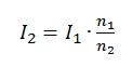
The trasduction of the current to the secondary voltage happens thanks to a terminating resistance RT. To limit the counter-electromotive force that is generated from the secondary to the measuring primary is necessary to make sure that the RT terminating resistor, both high and therefore for this purpose the number of the secondary coils must be chosen according to current ranges that we wish to measure.
Typically, they use these turns ratios
- Low current: Range from 0.5 A to 1 A = ratio 1: 100
- current Media: Range from 1 A to 10 A ratio = 1:50
- High current: Range from 0.5 A to 1 A = Ratio 1:25
The choice of the number of turns and the terminating resistor also affect probe bandwidth. The probe is terminated with an RG58 coaxial cable with a characteristic impedance of 50 ohms and must be used with the oscilloscope set with a DC 1Mega ohm input resistance.
The length of the coaxial cable does not affect the bandwidth of the probe for measuring the frequencies below 50KHz. Above 50KHz instead it is necessary to take into account the effect introduced by the low-pass connection.
DESIGN
In order to obtain a transducing ratio giving 1 Volt Ampere for each bed, utuilizzano the following formulas.
1.to the secondary current. The current to the secondary reading is equal to:
(1) 
2.Output voltage.The output voltage from the probe is equivalent to the product of the secondary current for terminating resistor
(2) 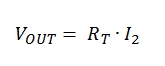
By substituting (1) in (2)
(3) 
3.Termination resistor. In order to read 1 Volt for each Ampere red (3) is expressed as :
(4) 
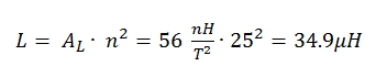
4.Inductance. Calculation of the inductance value:
(5) 
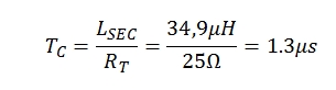
5.Time constant.The probe works in the linear regime until they do not have the saturation of the magnetic core. We must also consider the time constant of the probe introduces due to the value of the inductance and the terminating resistor. This time constant limits the maximum measurement frequency, because the magnetic field needs time to build and to collapse.
(6) 
6.
- Maximum frequency of the signal.The current probe to operate without distortion of a minimum period of 3 times greater than 3 times the Time constant TC :

(7)
- Magnetic Core characteristics of the probe designed with PCBway


PERF BOARD PROTOTYPE
Before proceeding with the routing of the circuit to be manufactured by PCBway it was decided to build a prototype of perf board. It was decided to use a plastic container for the containment of the probe and a RG58 cable with an impedance of 50 ohms for the connection with the oscilloscope.

Figure 2: Prototype made on Perf board
Routing PRINTED CIRCUIT
For the routing it was used the Altium Designer environment.

Figure 3: Environment routing Altium
The printed circuit board has been designed for the assembly of the termination resistor RT in SMD package, but it is also possible to mount the PTH resistance in exploiting the available pads.

Figure 4: routing current probe
ANALYSIS OF PRINTED CIRCUIT RECEIVED by PCBway
I want to emphasize the rapidity with which the printed circuit boards were produced and shipped from PCBway. In four days from the order I received the PCBs. I think the typical time is 7 working days, then in some fortunate cases can also be reduced. The quality of the PCB, in my opinion these are prototypes is absolutely acceptable. The following photos were performed via USB microscope and represent the main points where you can evaluate the quality of the process, such as vias, holes, screen printing, silkscreen, centering.

Figure 5: Box PCBway with PCB

Figure 5: First prototypes received from PCBway TOP side

Figure 6: First prototypes received from PCBway BOTTOM side
ASSEMBLY OF FIRST PROTOTYPE PCBway
To obtain an accurate value of the terminating resistor has been used the series of two resistors with values of 21.76 ohms and 3.3 ohms, obtaining a measured resistance of 25.06 ohms.

Figure 7: Creating terminating resistor RT
Then he proceeded to the welding on PCB PCBway of the toroid, resistors and RG58 coaxial cable.
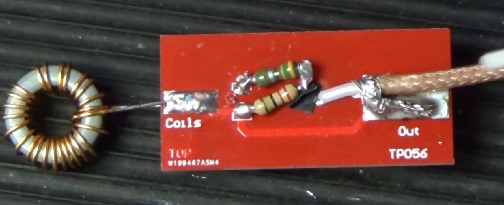
Figure 8: Mounting first prototype PCBway

Figure 9: Mounting first prototype PCBway in the container
TESTING THE FIRST PROTOTYPE PCBway
For the testing of the prototype it was used a fast IRPFZ44 MOSFET, can you to switch at frequencies of a few hundred KHz currents up to 5 Amps. The circuit is driven by a fiction generator Agilent 332210A.

Figure 9: Test Circuit
The current probe was positioned on the load connection.
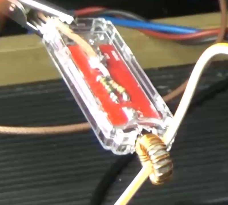
Figura 9: Test Setup wuth Probe designed with PCBway
With the frequency generator were generated square waveform with frequency from 1KHz to 300KHz.
 Figura 8: Function Generator
MEASUREMENT OF CURRENT ON THE FRONTS. With the scope of the current read data that are very precise we were evaluated. For example, in the following figure shows the switching of the MOSFET (blue curve) and the relative Drain current measured by the current probe (yellow curve). In this case the measured current reaches a peak of 1.7 ° (equal to 1.7 V on the oscilloscope beds) .The probe is an amperometric transformer coupling is AC, and then all the DC components will be cut.

Figure 10: TEST#1: current 1,5 A e frequency 1KHz

Figure 11: TEST#2: Current 2 A frequency 50KHz

Figure 12: TEST#3: Current 2 A frequency 100KHz
Final probe assembly is shown in the following figure.

Figure 13: Complete assembly of the probe designed with PCBway