


by PIER-ALESSANDRO AISA
Introduction
This article answers to a question that I am often find: “How do you measure high voltage, without avoiding the usage of a costly differential probe?”. Especially in the world of Tesla coils, of Cockroft Walton generators, Van der Graaf generators, it is often useful to have a small economical tool, to be used to measure voltages of several thousand Volts. The project presented in the following pages was developed in collaboration with PCBWay, the world’s leading manufacturer of printed circuit, with the best cost position \ quality \ quick delivery. In the next few paragraphs will detail all the steps necessary for the development of this project. And in particular
- Design and insertion of electrical scheme
- Routing of the printed circuit board
- Order to PCBWay 10 prototypes for fast prototyping
- Installation and testing of the first prototype
DESIGN
The following input data were used:
- Maximum input voltage 5,000 V
- Maximum operating frequency = 1MHz
- Overall dimensions compatible with a probe type tool houses
- Development of a low cost product
The basic scheme is an attenuator, which uses the voltage drop of the resistors to present at the output a voltage with a configurable attenuation ratio with respect to the input. Considering that the object will be cooupled with laboratory instruments, such as multimeters or oscilloscopes it is assessed that the output impedance of the instruments should take into account the input impedance connected to it. Figure 1: Wiring diagram
Two possibilities are available for the usage of this scheme and then the same printed circuit board with a different mounting:
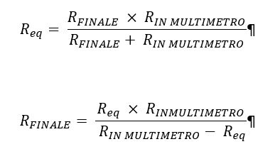
- In Parallel: Use the attenuator in parallel configuration to a measuring instrument for a known impedance input and in this case the final resistance, the one to which it connects the instrument must have a value such that:
Considering a maximum voltage equal to 5.000V the following have been selected:
- 9 resistances of the value of 1 megohm
- 1 resistance value of 1.11 mega ohms
In this way the maximum current flowing in the divider is equal to 5.000V / 10:11 megohms = 500uA
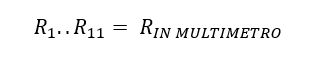
- In Series: Use the attenuator in series with one of high input impedance measuring instrument known and in this case all the resistors R1 to R10 must have the same value of the input resistance of the multimeter, namely:
Considering a maximum voltage equal to 5.000V have been selected:
- 9 resistances of the value of 10 megohms
In this way the maximum current flowing in the divider is equal to 5.000V / 10 megohms = 50uA
PROTOTYPE ON PERF BOARD
Before proceeding with the routing of the circuite it was decided to build a prototype of perf board.
 Figure 2: Prototype realized on Stripboard
Routing of PRINTED CIRCUIT BOARD
For the routing was used Altium the environment
 Figure 3: Environment routing Altium
Different solutions were tested in order to maximize the insulation distances, that a project of this type can make a difference. Ideally, the dielectric strength of air is 3KV / mm at atmospheric pressure at sea level and at a temperature of 20 ° C.
Consequently, a distance of 2 mm air is would be sufficient to keep the 5KV. But in this project, we made sure to raise as much as possible the distances mantenento an acceptable form factor to have an object that is contained in a small box with the probe.
 Figure 4: First routing attempt

Figure 4: second routing attempt
 Figura 5: Millings
ANALYSIS OF PRINTED CIRCUIT RECEIVED by PCBWay
I want to emphasize the rapidity with which they were produced and shipped printed circuits. In four days from the order I received the PCBs. I think the typical time is 7 working days, then in some fortunate cases can also be reduced. The quality of the PCB, in my opinion these are prototypes is absolutely acceptable. The following photos were performed via USB microscope and represent the main points where you can evaluate the quality of the process, such as vias, holes, screen printing, silkscreen, centering.

Figure 4: First prototypes received from PCBWay

Figure 5: first prototype received from PCBWay mounted and ready for testing
TESTING THE FIRST PROTOTYPE received by PCBWay
To verify the correct operation of the probe HT it was decided to supply power using a voltage of 800 volts alternating at 50Hz and to carry out the reading of the voltage using a multimeter.

Figure 6: Measurement of a voltage equal to 802 Vac 50Hz
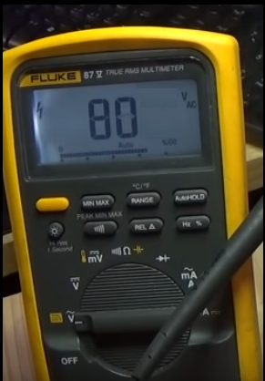
Figure 7: Measurement of a voltage equal to 802 Vac 50Hz, via the probe HT